Our Location
304 North Cardinal St.
Dorchester Center, MA 02124
304 North Cardinal St.
Dorchester Center, MA 02124

Choosing the right rake angle isn’t just about picking a number from a chart—it’s about understanding your material, machine, and machining goals. Here’s a practical approach to selecting the optimal rake angle for your specific project:
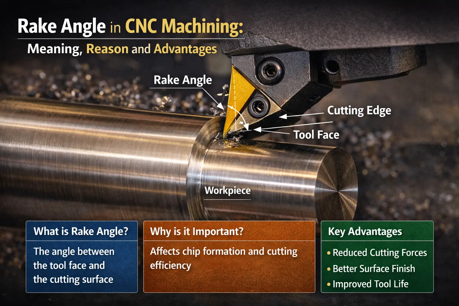
In our previous article, we explained what rake angle is and how it influences cutting forces, surface finish, and tool life in CNC machining. However, understanding the definition is only the first step. In real-world manufacturing, the more critical question is how to choose the right rake angle for your project.
Different materials, machining methods, and performance requirements call for different rake angle geometries. Is a larger rake angle always better? How should you balance cutting efficiency, chip evacuation, and tool strength?
In this article, we will take a deeper look at what are the recommended rake angles for different materials, including aluminum, stainless steel, carbon steel, and brass. We will also discuss the advantages and limitations of various rake angle selections in practical machining scenarios.
In addition, rake angle is a topic frequently addressed in our FAQ section, as it is often overlooked but plays a crucial role in machining performance. Understanding how rake angle relates to material type, cutting conditions, and surface requirements can help avoid common machining issues and ensure more consistent results.
👉 If you haven’t read our previous guide on rake angle basics, we recommend starting there to gain a clearer understanding before continuing with this article.
Soft and ductile materials (aluminum, copper, plastics) benefit from positive rake angles (+5° to +25°). They reduce cutting forces, produce thinner chips, and improve surface finish.
Medium hardness steels (carbon steels, alloy steels, standard stainless) are best suited to neutral/zero rake angles (0°), offering a balance between cutting efficiency and edge stability.
Hard and abrasive materials (high-carbon steel, hardened cast iron, superalloys) require negative rake angles (–5° to –20°) to maintain edge strength and resist chipping.
Roughing / heavy cuts: Choose neutral or negative rake angles for maximum tool strength. Positive rake angles can wear too quickly under heavy load.
Finishing / high-speed cuts: Positive rake angles provide smoother chip flow, reduced cutting forces, and better surface finish. Use chip breakers if needed to control long chips.
Interrupted cuts or hard alloys: Negative rake angles help prevent edge chipping under shock loads.
Low-rigidity machines or setups with long tool overhangs benefit from neutral or positive rake to minimize vibrations and chatter.
High-rigidity CNC machines can handle negative rake angles even under aggressive cuts, provided the spindle can supply sufficient torque.
Carbide and coated tools: Can handle steeper positive or negative rake angles and higher cutting temperatures.
High-speed steel (HSS): Requires moderate rake angles to prevent edge deformation and excessive wear.
Positive rake: Produces thinner, curled chips—easy to evacuate, ideal for ductile metals.
Neutral rake: Generates long, continuous chips—use chip breakers to avoid chip tangling.
Negative rake: Creates thick, self-breaking chips, perfect for brittle or hard materials.
Even within recommended ranges, small adjustments can have a big impact:
Reduce rake slightly if you see edge chipping.
Increase rake if cutting forces are too high or the surface finish is rough.
Always monitor tool wear, chip formation, and part quality after each change.
Key Takeaway: Selecting the right rake angle is an iterative process. Start with material-based recommendations, then refine based on cutting behavior, machine rigidity, and desired surface finish.
Mastering this subtle variable can unlock longer tool life, smoother operations, and higher efficiency—all without changing the machine or tool type.
The normal rake angle is defined as the rake angle measured in a plane that is perpendicular to the cutting edge. Unlike axial or side rake angles, which follow specific tool orientations, the normal rake provides a geometric reference across various cutting conditions and is essential for analyzing shear-plane formation and chip flow.
This angle plays a critical role in chip formation and determines the effectiveness of chip curling. For plastics like acetal, a normal rake between +15° and +30° promotes cleaner shearing and minimal heat buildup.
When drilling acrylics, a 0° normal rake helps maintain dimensional accuracy without melting or tearing. For hardened steels, normal rake is typically negative, around 5°, to preserve edge strength and manage cutting temperature.
By adjusting the normal rake, you directly influence chip thickness, shear deformation, and the cutting tool’s resistance to crater wear.
The rake angle is not a fixed value; it is adjusted differently depending on the machining operation being performed. Turning, milling, drilling, broaching, and sawing define and apply the rake angle in unique ways, depending on how the cutting tool interacts with the workpiece.
In turning operations, the rake angle is typically divided into the side rake angle and the back rake angle, both of which control the chip flow direction and shear deformation. In milling, both the axial and radial rake angles come into play.
For example, many end mills use a neutral radial rake angle combined with a positive axial rake angle to balance cutting forces and improve surface finish. When working with thermoplastics or soft aluminum, end mills with positive rake surfaces can reduce heat generation and decrease power requirements.
Broaching uses a progressively increasing positive rake angle from tooth to tooth. This gradual increase helps manage cutting force and chip thickness along the tool’s path. Saw blades for aluminum typically have a rake angle between +12° and +25°, which facilitates chip breakage and reduces tool wear during continuous feed operations.
Once you understand how the rake angle is applied in different processes, you can optimize your settings for better performance, whether cutting stainless steel or drilling acrylic. In turning, for example, using a positive side rake angle of +12° to +25° on aluminum improves chip evacuation and reduces cutting forces. This extends tool life and decreases heat buildup on the rake face.
In drilling, especially with deep-hole twist drills, rake angles can reach up to +40° to improve chip flow and prevent jamming.
For milling gray cast iron, a radial rake angle of +5° with a neutral axial angle stabilizes the loads on the insert and maintains surface integrity. When sawing mild steel, tooth rake angles around +12° to +14°, combined with a fine pitch, ensure balanced chip formation and controlled feed.
Thermoplastics present particular challenges. When drilling them, a nose angle between 90° and 118° is required, along with a rake angle of +10° to +30°, to prevent melting and deformation of the material.
It is not possible to apply a universal rake angle to all materials. Instead, it needs to be adapted according to the material properties, the type of machining operation, and even the cutting tool material.
The rake face and cutting edge must work in harmony with the tool geometry and the material strength to achieve efficient chip formation and minimal tool wear. Factors such as feed direction, tool strength, heat generation, and machinability directly influence the appropriate configuration.
For reference, the following are optimal rake angle values commonly used in various cutting operations:
Aluminum: Turning +12°–25°, Drilling +40°, Milling +35°, Sawing +12°–25°
Low-carbon steel: Turning +12°–14°, Drilling +20°, Milling +8°–15°
High-carbon steel: Turning –5° (often negative in finishing operations)
Titanium alloys: Turning 0°–+4°, Drilling 0°–+10°
Gray cast iron: Turning 0°–6°, Drilling 0°, Milling +5°
Plastics (PEEK, ABS, PVC): Rake angle +10°–30°, Clearance angle +8°–12°, Point angle 90°
Inconel 718: Positive rake angle of +10° with rounded edge
Whether you’re cutting metal, plastic, or composites, each tool face must be set at the correct angle to efficiently direct chips and reduce cutting forces. The rake angle can be built directly into the cutter design or adjusted by grinding the tool. Equally important is that the setup allows for precise alignment with the reference surface and the master line.
To properly prepare, measure, and maintain the tool’s rake angle, you’ll need a variety of equipment:
CNC lathes with tool turrets: For single-point tools and inserts with adjustable rake angles
Vertical and horizontal machining centers: Compatible with indexable or solid carbide cutters
Drill grinders: Capable of modifying the helix angle and rake angle for high-speed drilling
Metal-cutting band saws: With set teeth or carbide-tipped teeth designed with the correct face angle
Profile grinders: For resharpening high-speed steel (HSS) tools with precise rake geometry
3D optical profilometers: For verifying rake, clearance, and wedge angles without contact
Laser profiling systems: Used to modify the rake angle on micro-tools or coated inserts
Milling toolholders With angle shims: Adjustable shims for fine-tuning axial tilt
The rake angle directly influences the durability of the cutting tool and the frequency with which it requires maintenance. Choosing between a positive or negative angle affects the main wear modes, such as crater wear, edge chipping, and flank erosion.
When machining soft alloys with a positive, sharp rake angle, shallower crater wear zones may be observed on carbide tools, provided the cutting edge thickness can support the applied load.
Conversely, negative rake angles are more suitable for demanding conditions, such as interrupted cuts or materials with forging scale. These angles delay chipping by increasing edge strength and distributing cutting forces over a wider contact area. However, the disadvantage is a greater concentration of heat on the cutting face, which can accelerate wear due to temperature and diffusion.
To maximize tool life, maintenance cycles should be aligned with the dominant wear pattern. For example, tools with aggressive positive rake angles require earlier flank wear inspections, while those with negative rake angles need closer attention to edge strength and thermal effects.
This geometric feature appears in multiple industries, from precision manufacturing to medicine, wherever there is a need to cut, scrape, or remove material in a controlled manner. The rake angle defines how the cutting tool interacts with the workpiece, directly influencing chip formation, tool wear, and surface quality.
In manufacturing, an optimized rake geometry is critical for producing components such as aerospace turbine blades and automotive engine blocks. The cutter’s rake surface must be precisely aligned with the reference plane to minimize resistance and maximize chip flow direction.
Electronics manufacturing also relies on carefully tuned angles. V-shaped milling cutters used in PCB manufacturing employ steep positive rake angles to cleanly cut rigid FR-4 substrates.
Even in the medical field, the rake angle plays a key role. Endodontic files in dentistry incorporate a gentle positive rake angle to remove dentin uniformly without causing microfractures. In woodworking and composite material trimming, controlling the cutting edge angle is essential to prevent material tearing and maintain dimensional accuracy.
These applications demonstrate that the rake angle is not just a number, but a strategic decision that affects the material removal rate, tool life, and how cleanly the chip is removed.
Start with the basics. The side rake angle and back rake angle are fundamental in turning and general machining. In milling, axial and radial rake angles are used, often adjusted by inserts or the tool face geometry. In orthogonal cutting, the normal rake angle describes the angle measured in a plane perpendicular to the cutting direction.
It is also necessary to consider the rake angle and the clearance angle, which determine how sharp the tool edge is and how effectively it separates from the machined material. These angles, combined with the shear deformation behavior, control the cutting forces and chip thickness.
The material is also a decisive factor. Brittle metals like cast iron tolerate negative rake angles as low as -10°, while ductile materials like aluminum can benefit from positive values up to +25°.
In manual setups, machinists typically use contact goniometers or universal tool grinders to verify the rake angle, achieving an accuracy of approximately ±0.5°. These tools are suitable for larger cutters and traditional processes.
For more delicate geometries, optical comparators project the contour of the cutting edge onto a screen, enabling measurements with an accuracy of ±0.2° without physical contact.
Advanced methods, such as 3D optical profilometers, can scan the entire peel surface in less than a second. These systems generate height data with an accuracy of ±2 µm, calibrated in XYZ space using traceable standards.
Although still in use, probe profilometers can lose information on sharp edges due to the probe lifting above 60°. To ensure measurement repeatability, JCSS-certified calibration blocks and calipers are regularly used within inspection processes.
Rake Angle Formula
To optimize machining performance, it is essential to understand how geometry translates into cutting behavior. In orthogonal cutting, the rake angle (γ) directly influences the shear plane angle (φ), which determines chip thickness and cutting efficiency.
The approximate formula is:
φ ≈ 45° + (γ / 2) – (β / 2),
where β is the wedge angle. As φ increases with a higher positive rake angle, the chip thickness decreases, improving the material removal rate.
The chip thickness ratio (r) also depends on φ:
r = t₁ / t₂ = sin φ / cos(φ – γ)
where t₁ is the thickness of the uncut chip and t₂ is the thickness of the deformed chip. A higher value of r indicates thinner chips and lower cutting edge strength.
Tool designers use these relationships to predict cutting forces using:
F ≈ K · t₂ · w
where K is a material-specific constant and w is the width of cut.
Even with theoretically ideal geometry, actual machining can indicate when the rake angle setting is not working correctly. One of the first signs is a sudden increase in spindle load, often exceeding 20% of the baseline value. This indicates high resistance at the cutting interface.
Audible rattling or vibration often follows, signaling instability in the chip flow direction or cutting edge behavior. If you observe powdery or inconsistent chips instead of controlled, curled chips, the rake angle may be too blunt or too aggressive for the material.
Tool wear is another key indicator: excessive flank wear greater than 0.3 mm in less than 10 minutes, or a crater depth greater than 0.2 mm on the rake face, suggests that the angle is not aligned with the tool material or process parameters.
Surface finish also tells the story. If the Ra value is double the specification or torn fibers appear on composite parts, it’s time to re-evaluate the rake angle geometry.
What factors influence rake angle selection?
The first factor to consider is the workpiece. Hard or brittle metals like cast iron and certain stainless steel alloys favor negative rake angles, which offer greater edge durability. Conversely, soft and ductile materials like aluminum allow for more aggressive positive rake angles to promote smoother chip flow.
The tool material is also crucial. Carbide tools typically perform well with neutral or negative rake angles. Polycrystalline diamond (PCD) inserts, on the other hand, rely on highly positive rake angles to cut with less resistance.
Machine rigidity, spindle power, and even coolant availability influence whether the setup can handle sharp or blunt rake angles.
The type of operation also plays a significant role. Roughing operations require longer-lasting cutting edges, so a neutral rake angle is usually preferred. Finishing operations, where surface quality is paramount, typically benefit from positive rake angle setups. If your tool incorporates a chip breaker, its geometry must be coordinated with the rake face to direct the chips cleanly and in a controlled manner.
From surface finish objectives to feed direction and tool geometry, almost every variable in precision machining is directly related to the correct selection of the rake angle.
The cutting tool material sets the limits of how steep or flat the rake angle can be. This relationship cannot be ignored, as the rake surface interacts directly with the workpiece, and an incorrect combination of tool material and rake angle can shorten tool life or even ruin the workpiece.
If you are using high-speed steel (HSS), a positive rake angle between +8° and +18° typically works best. This allows the tool to maintain its edge at moderate cutting speeds, especially when working with general-purpose steels or composite sections. The toughness of HSS benefits from sharper cutting edges, which reduce cutting resistance.
Uncoated carbide, on the other hand, performs better on hard steels with neutral or even negative rake angles, sometimes as low as -10°. Its resistance to heat and deformation allows machining at higher speeds without catastrophic tool failure.
Ceramics and cubic boron nitride (CBN) operate with even more negative rake angles (-10° to -20°), especially in high-speed finishing of hardened components, where edge strength is critical.
How does power consumption relate to the rake angle?
The rake angle directly influences the power consumed during machining, especially in high-volume production environments, where small changes are quickly amplified.
Using a positive rake angle typically reduces the cutting force coefficient (Kc). As a result, the energy required to shear the material decreases. In many machining tests, cutting energy is reduced by approximately 15% when moving from a neutral to a more positive rake angle, especially with ductile metals.
Conversely, negative rake angles increase resistance at the cutting edge.
On machines with a power rating of 30 kW, a 5 to 10 amp increase in spindle current can be observed, especially when machining high-strength alloys. This additional load results in more heat, accelerated tool wear, and potential instability in the chip flow direction.
If you conduct energy audits per part or are seeking to meet sustainability goals, adjusting the rake angle is one of the most immediate ways to reduce energy consumption without compromising surface finish or accuracy.
Hastyening the setup or using a generic tool without considering the specific process risks tool breakage, poor chip evacuation, or surface finish defects. Many of these errors stem from ignoring the relationship between tool geometry and the machining environment.
A common mistake is applying a highly positive rake angle to hard materials such as tool steel or hardened stainless steel. This can lead to premature chipping of the cutting edge, especially under high-speed or dry-cutting conditions.
At the opposite extreme, using negative rake angles on low-power machines can overload the spindle and reduce cutting efficiency. In these cases, increased energy consumption and vibration are typically observed.
It is also common to overlook the chip breaker design. When machining ductile materials with a positive rake face, chips can become long and continuous if they are not redirected by a properly aligned chip breaker. Another often-overlooked factor is the clearance angle: if the rake face is too steep relative to a small clearance, flank rubbing can occur, increasing temperature and wear.
Adjusting the rake angle when changing the depth of cut is also critical. As more material is removed, the chip thickness increases, requiring adjustments to the rake angle or reinforcement of the cutting edge to prevent overloading.
Once the rake angle is correctly matched to the workpiece and tool material, it directly influences chip morphology and surface quality. Chip shape, flow, and consistency are directly related to the rake face and the interaction between the cutter and the material removal process. This interaction defines machining performance more than is often realized.
Consider the following:
Positive rake angles tend to produce continuous, curled chips, especially in aluminum alloys like 6061-T6. These smooth-flowing chips reduce heat generation, decrease cutting forces, and promote a fine finish, achieving surface roughness (Ra) values below 0.4 microns. This configuration is ideal when surface quality is the priority, especially in precision manufacturing applications.
Negative rake angles, on the other hand, produce segmented chips, particularly when machining brittle metals like cast iron or hard steels. Although these fragmented chips may appear less refined, they prevent built-up edges and offer greater surface consistency in certain materials. In many cases, a better surface finish is observed with less material buildup on the cutting edge, especially in dry machining.
At high speeds, the rake angle geometry becomes even more critical. A negative rake angle combined with a slightly rounded cutting edge can suppress vibration and improve stability. Although cutting forces increase, the greater resistance to vibration improves the final surface finish.
Depending on the tool type and machining operation, it is possible to adjust the rake angle to better suit the material removal conditions. In CNC machining, modifying the tool angle can improve chip formation, surface finish, and tool life. However, the degree of modification depends largely on the tool’s construction and geometry.
Solid carbide end mills can be re-fluted to change the axial rake angle. This allows for adjusting the chip flow direction and rake face contact without compromising cutting edge strength.
In brazed-tip tools, the rake face can be reground, typically within a range of ±2°, to improve cutting performance in various alloys such as tool steels or stainless steels.
Indexable inserts, however, are machined with a fixed rake geometry. Their top face cannot be modified, but the use of angled shims on milling cutters allows the axial angle to be varied up to ±5°. Even so, these configurations must respect the wedge angle, clearance angle, and alignment with the reference plane to ensure safe and efficient machining.
In advanced applications, especially in dental or surgical machining, laser ablation allows for the creation of micro-rake geometries on small tools. These adjustments are usually designed using 3D models that consider the tool geometry, chip deflection, and material strength.
Therefore, if you work in high-precision manufacturing, customizing the rake angle can give you a competitive advantage in accuracy, chip control, and machining performance.
Now that you know the rake angle can be adjusted, it’s equally important to understand what happens when it’s not optimized. Choosing an incorrect rake geometry not only affects the cutting edge’s behavior but also disrupts the entire machining operation and increases costs in the long run.
The excessive cutting forces generated by steep negative rake angles can increase the spindle load, raising energy consumption per part by up to 12%. This directly increases electrical costs, especially in high-volume production.
The additional stress on the cutting edge also causes premature tool failure, reducing tool life and increasing the tooling budget.
When chip formation becomes inconsistent, the resulting surface finish can fall out of tolerance, leading to costly rework. In precision manufacturing, even small variations in chip thickness or orientation can degrade surface quality and generate dimensional errors that reduce OEE.
Furthermore, an improper rake angle setting can increase vibrations. This accelerates wear on machine bearings and causes misalignment between the tool face and the reference surface. Over time, machine performance deteriorates, increasing the risk of tool damage and reducing accuracy in multiple operations.
When measuring the rake angle using traditional methods, accuracy and repeatability are often compromised, especially with tools that have complex geometries or small tips.
Probe contact profilometers tend to lose contact when moving over steep rake surfaces, leading to a significant underestimation of the actual angle. In some cases, shallow rake flanks can be measured with errors of up to 2°, especially when the rake face has irregular geometry or surface waviness.
Optical systems are not without limitations either. Microscope-based measurements introduce parallax errors, generating an uncertainty of up to ±1°, especially when aligned with the reference plane or the cutting tool’s guideline. This affects both positive and negative rake angles.
Another significant limitation is the complexity of the setup. In multi-edged tools, such as those used in precision CNC machining, fixing each edge in the correct orientation plane and perpendicular to the measuring axis is time-consuming.
This additional time reduces productivity, especially when working with tool steel, cast iron, or high-speed cutters, where the rake angle and chip flow direction are critical factors.
Obtaining accurate results when measuring the rake angle requires careful consideration of surface quality, measurement repeatability, and proper alignment of the tool with the cutting edge.
The rake angle directly influences how the chip separates from the workpiece. A more positive rake angle reduces cutting forces, which decreases heat generation and improves surface finish. Conversely, negative rake angles increase edge strength, but at the cost of increased cutting resistance and higher energy consumption.
The relief angle is the clearance between the tool flank and the machined surface.
If sufficient clearance is not maintained, the tool rubs instead of cutting, raising the temperature and degrading the edge strength. However, an excessively high relief angle reduces support near the cutting edge, weakening the tool tip.
The tool’s included angle must balance both the rake angle and the relief angle.
In hard materials such as stainless steel or tool steel, a larger included angle combined with a neutral or slightly negative rake angle is often necessary. This combination minimizes chipping and maximizes tool life, especially in operations requiring consistent chip thickness and precise directional control.
Properly adjusting the rake angle is not just a technical detail; it’s one of those small decisions that can make a difference.
It makes a huge difference to the smoothness of the machining process. When the tool geometry is matched to the material, chip flow, and machine setup, everything works better. Material is removed faster, tools last longer, and the resulting surfaces are cleaner.
However, even the theoretically perfect rake angle loses its value if it isn’t set and measured correctly. That’s why it’s crucial to check the rake face alignment, cutting edge angles, and even the tool tilt, especially when working with difficult materials or when aiming for an optimal surface finish.
If your current insert or cutter isn’t delivering the expected performance, don’t hesitate to adjust the settings or consult your tool supplier for a more suitable solution.
Ultimately, we’re not just cutting metal; we’re building reliability, precision, and efficiency into every part. Treat the rake angle as another tool in your toolbox, not just a value on a chart. Keep experimenting, keep testing, and you’ll get better results every time you press “start.”
No. The rake angle cannot be modified during the cutting operation. The tool geometry defines the rake angle, and once the tool makes contact with the workpiece, the rake face and the reference surface are fixed. Any modification, such as resharpening or replacing the tool, requires stopping the process.
A worn rake angle alters the chip flow direction and increases cutting forces. This results in higher energy consumption, increased heat generation, and vibration. Over time, it reduces tool life and surface quality, while accelerating edge wear and decreasing the material removal rate.
It depends on the material. Positive rake angles are ideal for ductile materials such as aluminum and plastics. Negative rake angles are preferred for hard or brittle materials such as stainless steel or cast iron, as they increase cutting edge strength and reduce the risk of chipping.
A large positive rake angle results in a thinner wedge angle and less resistance during cutting. However, it also weakens the cutting edge, making it more susceptible to premature failure, especially at high speeds or when machining abrasive materials.
In endodontics, a positive rake angle, typically around +15°, is used on instruments to gently scrape dentin. This design improves cutting efficiency and minimizes damage to the canal walls, ensuring a smoother procedure and better clinical outcomes.

CNC Machining & Rapid Prototyping Expert
Freja focuses on CNC machining, rapid prototyping, and metal finishing solutions, helping global customers bring precision parts from design to production.