Our Location
304 North Cardinal St.
Dorchester Center, MA 02124
304 North Cardinal St.
Dorchester Center, MA 02124

If you have ever wondered why one tool cuts through metal like butter while another seems to struggle with every millimeter, the answer often lies in a small but powerful detail: the rake angle. It’s the part of the cutting tool’s geometry that controls how the material is removed during machining.
Whether you’re CNC milling aircraft parts, shaping dental instruments, or trimming delicate circuit boards, choosing the right rake angle can make a huge difference to your operation’s performance.
Most rake angles fall between -15° and +25°, but there’s no one-size-fits-all solution. For example, drilling aluminum might require a sharper angle, up to +40°.
On the other hand, soft plastics like PVC or ABS respond best to angles between +10° and +30°. These differences are important: they influence chip evacuation, tool wear, and the amount of heat generated during the process.
And here’s the key point: simply adjusting the rake angle correctly can increase machining productivity by up to 20%, without spending a penny on new equipment.
So, if you’re serious about improving performance and getting the most out of your tools, this is the place to start. In this article, we’ll focus on how the rake angle affects machining, why it works, and how you can make it work better for you.
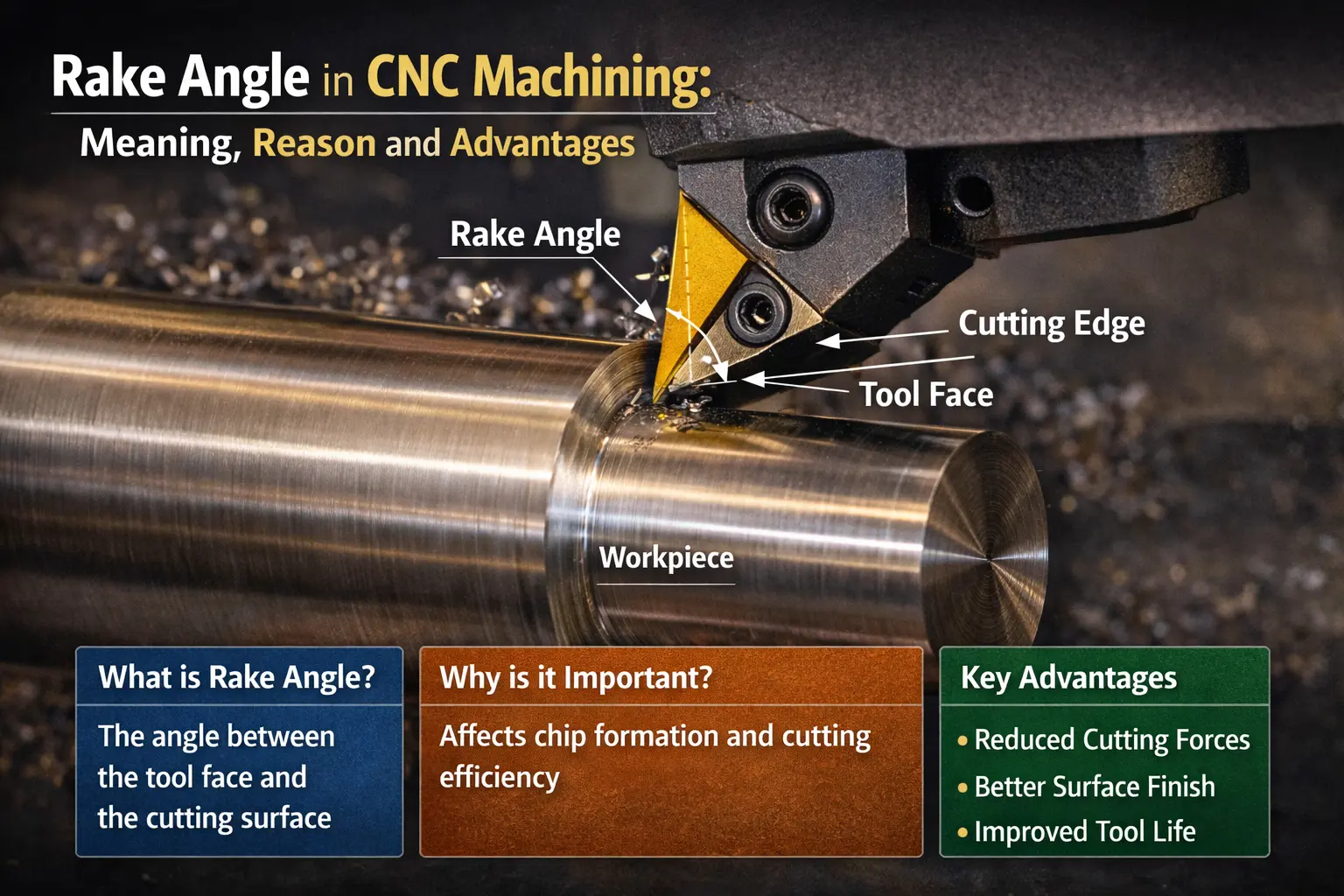
In CNC machining, the rake angle is the angle measured between the rake face of the cutting tool and a line drawn perpendicular to the cutting direction. This geometry directly influences how the cutting edge interacts with the workpiece and governs chip formation, cutting forces, and surface finish quality.
The rake angle varies depending on the tool type and application. For single-point tools used in turning operations, the lateral rake angle is typically specified.
In milling, both the radial and axial rake angles are defined, as each influences chip deflection and edge strength differently in various directions. The reference plane for these measurements is usually aligned with the feed direction and cutting speed vector.
In standard machining operations and processes, most rake angles fall between -15° and +25°, although tool materials and workpiece properties can extend this range. Plastics and aluminum may require steeper positive rake angles, while hard materials, such as tool steel or cast iron, typically prefer negative rake angles to preserve cutting edge integrity.
The choice between positive and negative rake angles affects everything from power consumption to surface finish. A positive rake angle produces a sharper cutting face and reduces cutting forces, while a negative rake angle increases tool strength by increasing the wedge angle.
The rake angle directly influences how the cutting tool interacts with the material, regulates chip flow, and determines the energy required for material removal. Even a small adjustment to this angle can completely change the machining outcome.
Tests performed on low-carbon steel have shown that changing the rake angle from -5° to +15° can result in up to a 30% variation in the required cutting power. This is not limited to energy consumption; it also directly affects tool wear and stability under load. A more favorable rake angle reduces cutting forces, allowing the machine to operate cooler and more efficiently.
A positive rake geometry produces thinner chips, which are more easily evacuated from the rake face. This reduces the risk of built-up edge formation and can improve surface finish by up to 40%.
At the same time, negative rake angles distribute the stress across a thicker wedge angle, improving tool life when machining hard metals. For this reason, many machinists double tool life on high-carbon steels simply by switching from +10° to -5°.
Tool geometry, production volume, surface finish requirements, and machine rigidity all influence the rake angle selection. It’s not just a theoretical value: this angle governs chip formation, cutting edge performance, and heat transfer between the tool and the workpiece.
A positive rake angle typically reduces the tangential cutting force by 10% to 25%, especially in ductile materials. This allows for greater material removal with less resistance, improving the material removal rate and reducing the overall load on the cutting edge.
On the other hand, cutting edges with a negative rake angle offer significantly greater strength. In transverse fracture tests, they have demonstrated up to 30% greater strength, making them ideal for interrupted cutting operations or for harder alloys. If you are machining tool steel or hardened stainless steel, a negative rake angle can help you extend tool life without changing inserts as frequently.
In real-world application data, carbide inserts used on high-carbon steel lasted 1.8 times longer at -5° than at +5°. A performance improvement of this magnitude cannot be ignored.
However, it is also important to recognize that an excessively positive rake angle—above +20°—can weaken the cutting edge. This leads to faster crater wear and more frequent resharpening cycles.
If you are looking to maximize tool life without sacrificing machining performance, the best strategy is to balance the rake angle so that crater depth and flank wear increase at similar rates.
Chip formation is one of the clearest indicators of whether the rake angle is working in your favor. A rake angle of +20°, common in aluminum machining, tends to produce clean, curved chips, similar in shape to the number six. These chips are easily evacuated and rarely clog the tool face, minimizing recutting and improving overall surface quality.
Moving to a rake angle of -5°, especially when machining brittle materials like cast iron, produces compact, fragmented chips that are cleanly removed. These are easier to manage in automated systems and reduce the need for chip breakers, especially in continuous production.
As the rake angle becomes more negative, the chip compression ratio increases. This increases shear deformation and heat generation, which can affect the edge condition and chip thickness. Conversely, a neutral rake angle typically produces long, ribbon-like chips that can clog the cutting zone and accelerate wear on the rake face.
Once the positive rake angle exceeds +15° in ductile materials, chip breakers become necessary to prevent tangled or stringy chips. Without them, you’ll end up untangling chips instead of finishing parts.
The rake angle is measured relative to the reference plane and determines the direction of chip flow. It defines how the cutting edge contacts the workpiece, influencing both shear deformation and force levels during machining.
Depending on the operation and the tool material, it is typically used within a range of -15° to +25°, although in special applications, such as drilling soft alloys, steeper values may be required.
The clearance angle, on the other hand, is the angle formed between the tool flank and the machined surface. Its function is simple but fundamental: to prevent the tool from rubbing against the workpiece.
While the rake angle influences chip control, cutting forces, and power consumption, the clearance angle focuses on minimizing friction and maintaining dimensional accuracy. Without a sufficient rake angle—for example, less than +3°—there is a risk of overheating, accelerated tool wear, and surface damage.
On the other hand, a rake angle greater than +15° can thin the wedge angle and reduce cutting edge strength.
If you are working with stainless steel or other materials prone to flank wear, increasing the rake angle from +5° to +10° can reduce tool degradation by approximately 15% without significantly affecting cutting efficiency. Together, both angles define the tool’s cutting geometry, influencing cutting edge strength, vibration stability, and the final surface finish.
Essentially, the rake angle determines the orientation of the shear plane and regulates how chips are generated and evacuated. It is the angle formed between the rake face and the reference surface, and it directly affects both the cutting and thrust forces acting on the tool tip.
When machining ductile materials such as aluminum or low-carbon steels, a positive rake angle promotes smoother chip flow and reduces the power required to shear the material. This not only improves the material removal rate but also reduces the maximum temperature in the cutting zone.
Less heat means less tool wear and, ultimately, a more consistent surface finish throughout its lifespan. In brittle materials, a negative rake angle creates stronger cutting edges by increasing the wedge angle, which is crucial for resisting microfractures during intermittent contact.
Beyond mechanical forces, the rake angle also influences chip flow direction and heat dissipation. A steep positive rake angle keeps chips away from the rake face, preventing secondary contact that causes crater wear. Conversely, a negative rake angle directs heat deeper into the tool, which can be acceptable if the cutting material is designed to withstand high temperatures, such as coated carbide or ceramics.
Choosing the appropriate rake angle is also related to vibration control. The resulting cutting speed vector is determined by the rake angle and can either stabilize or destabilize the machining process, especially at high speeds.
There are three main categories: positive, negative, and neutral (or zero) rake angles. A positive rake angle is formed when the sum of the wedge angle and the flank angle is less than 90°, creating a sharp cutting edge angled toward the workpiece.
This type is most effective for soft and ductile materials and is frequently used in high-speed machining of aluminum or plastics. The typical range is between +5° and +25°.
Negative rake angles occur when the sum of the wedge angle and the flank angle exceeds 90°.
In this case, the cutting face is angled away from the feed direction, increasing resistance but significantly improving tool life. This configuration is commonly used for tool steels, hardened cast iron, and nickel-based alloys, especially for ceramic inserts, where the rake angle can reach as low as -20°.
A neutral, or zero, rake angle positions the rake face perpendicular to the feed direction. This configuration simplifies tool manufacturing and is common in general-purpose inserts.
In milling, both the axial and radial rake angles are specified. A combination of a positive axial rake angle and a neutral radial rake angle is commonly used on aluminum alloys to improve chip flow direction and reduce tool wear. Ball-end milling cutters often incorporate a negative rake angle on the helix to strengthen the core and extend tool life during contour machining.
A positive rake angle reduces the thickness of the cutting wedge, creating a sharper cutting edge that penetrates the material more easily. This geometry is ideal for machining aluminum, copper, titanium, or low-carbon steels, especially when a good surface finish and reduced cutting forces are required.
Typically, this angle is between +10° and +25°, with aluminum alloys preferring values near the upper end of the range. When machining titanium, a slightly smaller positive rake angle, around +10°, helps reduce built-up edge formation without compromising edge strength.
On single-point tools, a side rake angle of up to +25° is common in soft plastics like PVC, where minimal strength and a clean cut are critical.
The main benefit of a positive rake angle is its shearing action. By reducing the force required to remove material, it decreases spindle load and energy consumption. This allows lighter machines to achieve high machining performance without excessive wear.
However, an excessively positive rake angle without proper chip control can lead to problems such as built-up edge formation.
or chip tangles. To avoid these, it is advisable to combine the rake angle design with a chip breaker geometry when necessary.
Using a positive rake angle offers multiple advantages, especially when seeking high material removal efficiency and improved surface finish:
Despite its advantages, a positive rake angle isn’t always the best option, especially under aggressive cutting conditions or with hard and abrasive materials:
A negative rake angle refers to a tool geometry where the rake face of the cutting tool is angled away from the feed direction, increasing the included wedge angle. This configuration strengthens the cutting edge, making it ideal for demanding applications.
A negative rake angle is commonly used when machining hard and abrasive materials such as high-carbon steels, hardened cast iron, and certain superalloys.
For example, turning tools used to machine gray cast iron typically incorporate a side rake angle of -5°. In more aggressive environments, ceramic inserts used for nickel-based alloys can go even further, featuring rake angles of -10° to -20°. These extreme geometries help the cutting tool resist chipping and maintain edge strength even under high temperatures and intermittent loads.
You should consider a negative rake angle when tool life and durability are more critical than cutting efficiency.
This geometry allows tools to operate at high speeds without rapid degradation, especially in roughing operations or when machining tough alloys where edge stability is the dominant performance factor.
Using a negative rake angle offers several durability benefits, particularly under high-force or high-temperature machining conditions:
Although the negative rake angle increases edge strength, it also presents challenges that must be managed, especially when machining soft or ductile materials:
The neutral rake angle, also known as the zero rake angle, occurs when the tool’s rake face is perpendicular to the feed direction. In this configuration, the rake angle is 0°, placing it exactly between positive and negative geometries.
This type of geometry offers a balance between cutting capacity and edge strength, making it a versatile choice for a wide variety of general machining applications. It is frequently used in universal indexable inserts, where simplicity of design and repeatable performance are key factors.
The neutral rake angle is commonly used in turning and milling operations when working with medium-hardness materials, such as standard carbon steels, alloy steels, and certain stainless steels. It is also suitable for processes where a compromise between surface finish and tool life is required.
From a mechanical standpoint, a neutral rake angle generates higher cutting forces than a positive rake angle, but lower than those associated with a negative rake angle. This provides greater edge stability without requiring an excessive increase in power. On CNC machines with moderate rigidity, this geometry helps maintain stable and predictable cutting behavior.
Regarding chip formation, a zero rake angle tends to produce longer, more continuous chips that can be difficult to evacuate, especially in ductile materials. For this reason, inserts with a neutral rake angle often incorporate chip breakers to improve chip control and reduce the risk of chip trimming or accumulation.
From a thermal perspective, the neutral rake angle distributes heat more evenly between the tool and the workpiece. This reduces the likelihood of extreme crater or flank wear, provided that proper cutting conditions and effective cooling are maintained.
In applications where process consistency, cutting edge robustness and flexibility of use are more important than maximum material removal efficiency, the neutral rake angle represents a practical and reliable solution.
A neutral rake angle offers several practical advantages, especially in general machining applications where stability and versatility are required:
Despite its versatility, the neutral rake angle also has limitations that must be considered:
| Rake Angle Type | Typical Range | Recommended Materials | Main Advantages | Main Disadvantages | Common Applications |
|---|---|---|---|---|---|
| Positive | +5° to +25° (aluminum up to +25°) | Soft and ductile materials: aluminum, copper, titanium, soft plastics |
– Lower cutting forces – Better surface finish (20–40% Ra) – Improved chip evacuation – Higher feed rates possible |
– Lower edge strength – Long/stringy chips without chip breaker – Faster wear in abrasive materials |
High-speed milling of aluminum, plastic turning, light roughing |
| Neutral / Zero | 0° | Medium hardness materials: carbon steels, alloy steels, standard stainless steel |
– Balance between edge strength and cutting efficiency – Higher process stability – Simple and robust design – Good thermal distribution |
– Higher cutting forces than positive rake – Long chips if no chip breaker – Lower high-speed machining efficiency |
General-purpose inserts, standard turning and milling, workshops with multiple materials |
| Negative | –5° to –20° | Hard and abrasive materials: high-carbon steel, hardened cast iron, superalloys |
– Higher edge strength – Better chip control in brittle materials – Supports high cutting speeds in hard materials |
– Higher cutting forces and spindle load – Greater heat concentration – Rougher surface finish in soft materials |
Aggressive roughing, hard steel machining, cast iron, ceramic inserts for nickel alloys |
Rake angle is rarely the first variable adjusted when machining performance drops—but it should be. Subtle changes in rake geometry can quietly influence cutting forces, heat distribution, vibration behavior, and long-term tool stability.
What makes rake angle especially challenging is that its effect never exists in isolation. Feed rate, cutting speed, tool coating, and material microstructure all interact with rake geometry in ways that aren’t always obvious on the surface.
That’s why selecting the “right” rake angle isn’t a one-time decision—it’s part of a broader optimization process.
In the next section, we’ll look beyond rake angle alone and explore how tool geometry and cutting parameters work together in real machining scenarios—and how small adjustments can unlock measurable improvements in tool life and surface quality.

CNC Machining & Rapid Prototyping Expert
Freja focuses on CNC machining, rapid prototyping, and metal finishing solutions, helping global customers bring precision parts from design to production.